With the defective transmission finally removed from our Impala SS, it's time to tear it down to inspect for damage and replace any components that are deemed defective.
Although we usually shy away from messing with automatic transmissions, manuals are usually simple enough to be serviced with a normal assortment of hand tools and perhaps a trip or two to the local rental store. Follow along as we break down our T56 into its constituent components.
Sharp-eyed readers may note that this transmission is cleaner than the one we showed in our previous installment. This particular T56 specimen here is from a 2006 Chevrolet SSR, and we're tearing it apart to see what parts, if any, we can use to reinforce our mishmash of F-body and Viper parts.
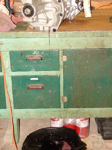
Normally, the transmission would have been drained before removal from the vehicle, but it's a good idea to pull the plug once again to get out any remaining fluid.
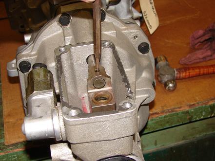
First, we need to knock out the roll pin that holds the shifter cup to the shift rail. This will allow the cup to slide off the rail when we pull off the tailshaft housing.
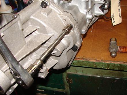
Next, we remove the bolts that hold the tailshaft housing to the transmission case.
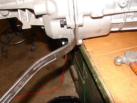
Since RTV or an anaerobic sealer is used in lieu of a gasket, a bit of gentle prying is usually required to separate the tailshaft housing from the case. Tremec is kind enough to provide a couple of slots to make this task easier. Make sure not to mar the sealing surface of either component while doing this.
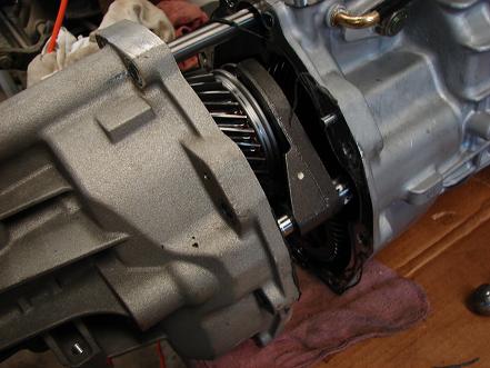
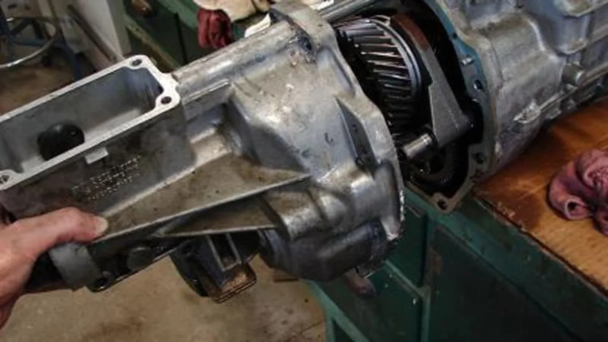
Slide off the tailshaft housing and set it aside. Expect to find some transmission fluid that wasn't completely drained in the prior step (note the rag we've placed under the junction of the case and tailshaft housing).
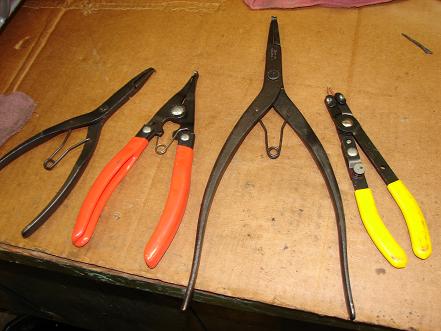
Starting at this point, we'll need an assortment of snap ring pliers. Not only will we need the usual "pin" style for external snap rings, but also required are a couple robust set of transmission snap ring pliers. Here, we use a pair from Craftsman and a couple of pairs that came from Snap-On.
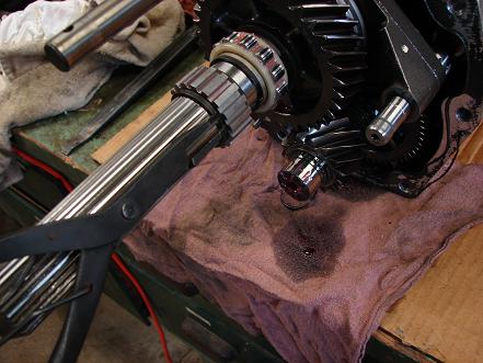
Start by removing the snap ring that retains the reluctor ring for the vehicle speed sensor.
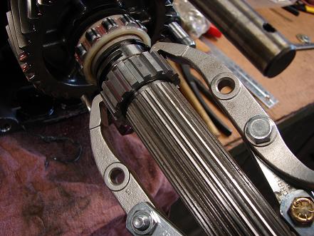
Using a two-jaw puller, remove the reluctor ring. While it may be tempting to start wacking away with punches and a hammer, resist the temptation, for it will usually result in damaged parts and a potential safety hazard from flying metal chips.
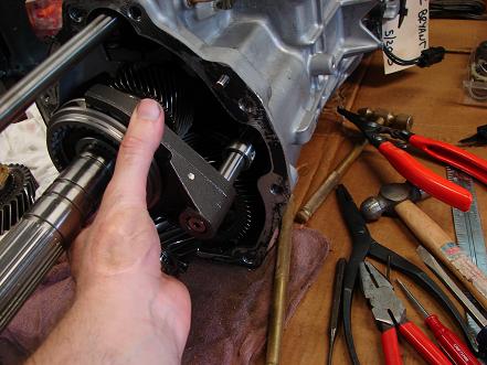
Now we remove the Reverse synchronizer and driven-gear assembly, along with the Reverse shift fork.
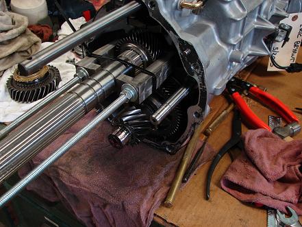
Due to the length of the mainshaft, we fabricated this puller a while back to remove the 5th-6th driven gear. One may consider the custom fabrication of tools as a sign that one works on a particular assembly way too often.
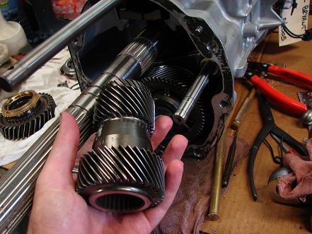
The 5th-6th driven gear is slid off the mainshaft and set aside.
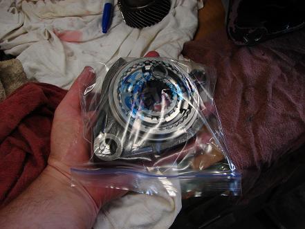
As components and subassemblies are removed, we place them in Ziploc bags. Not only can we label the bags and keep things sorted out, but it also serves to keep the components clean. This is especially important when moving at our typical pace on this sort of projects, which usually involves disassembled parts sitting around for several months as we determine our next step and find somewhere else to get into trouble. Call it "gearhead ADD".
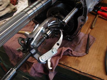
The Reverse drive gear assembly is pulled from the countershaft.
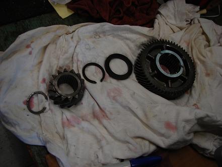
Here, we've also pulled off the 5th drive gear and set it aside.
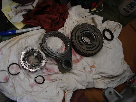
The 5th/6th synchro assembly and 6th drive gear come off next. Note that a double synchro assembly is used here for the overdrive ratios, where as our F-body/Viper T56 using a single cone synchro for these gears.
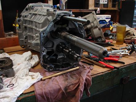
We've now removed everything that used to reside in the tailshaft housing, which is the Reverse, 5th, and 6th gear assemblies. From an assembly standpoint, one can think of a T56 as a traditional four-speed with an overdrive added on (this isn't actually how it was developed, but it's how it's built).
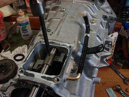
A roll pin must be driven from the detent lever to free it from the shift rail before proceeding.
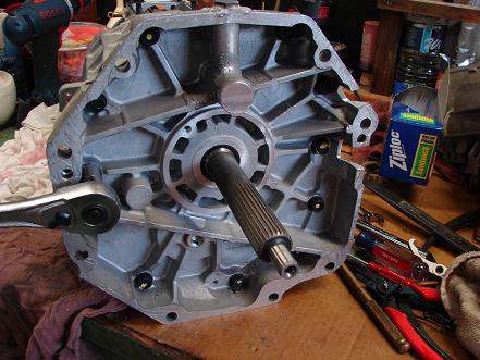
Next, we loosen all of the bolt securing the "midplate" (which is actually the front of the tranmission) to the case. Remove all but two of the bolts.
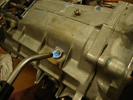
We apply some heat and penetrating oil to the shift rail guide bolts to break down the threadlocker that was applied during assembly.
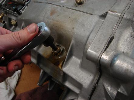
Using a T40 Torx driver (or several, depending on how many we manage to break), we loosen but do not remove the guide bolts.
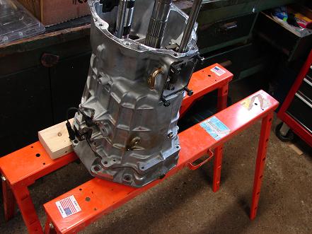
With two bolts still holding the midplate to the case, lift the transmission off the bench and secure it to a transmission stand; if one is not available, a pair of robust sawhorses works well.
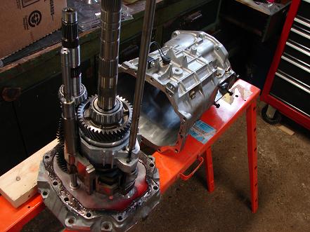
Pull out the two remaining bolts, completely remove the shift rail guide bolts, and lift the case from the midplate. As was the case with the tailshaft housing, some gentle prying may be required to break loose the sealant between the case and the midplate.
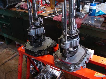
With the case removed, the mainshaft, input shaft, counter shaft, and shift rails are revealed. Each of those components can be carefully lifted from the midplate and set on the workbench. Start by pulling out the 5/6/Reverse rail (to the right side of the trans), and then remove the main shift rail and mainshaft as one subassembly. Finally, the countershaft and input shaft can be pulled out and set aside.
We then repeated the process a second time on the transmission that was removed from the Impala.
In the next installments, we'll take a closer look at each of the components to show how they work together to provide each gear ratio (and Reverse, of course). The broken parts in the Impala's transmission will be examined to see if we can find a cause for the failure. We'll also compare the components of each transmission in an attempt to build up something stronger. Stay tuned...

Sign in to post
Please sign in to leave a comment.
Continue